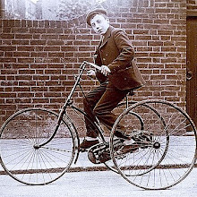
Here's a new design I have been working on.
Thursday, October 22, 2009
fold up design
Here's a new design I have been working on.
Thursday, September 17, 2009
internal hub cvt
Sunday, September 6, 2009
Kickstarter
Friday, July 17, 2009
HUMAN POWERED VEHICLE
 If you ever had a gyroscope as a kid you can see how similar this kind of principle works. The rear wheels are like gyroscopes being pulled while the string is held in a fixed position. Figure 1A is an isometric view, 1B is the front view, 1C is the side view, 1D is the top view, 1E is a detailed sketch of the rear.
Top detail
Top detail sketch showing a rocker arm (38) that supports and allows limited movement of the slide bars (46 and 48).
Detail 3
Here is a detail sketch of a rear wheel showing a large torsion spring (82) that coils up the cable each time that side is drawn forward. The constant tension that the cable would be under will also help assist the rider in returning the rear wheel forward.
Embodiment 2
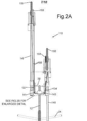
Figures 2A and 2B show the second embodiment and a detail shot. The cables are anchored at the opposite slide bar to give the operator the ability to alter the speed of the vehicle by changing the pattern of movement of the legs. For example, if you were to operate the vehicle where the legs moved in constant opposition (just like walking or running)this would be low gear. If you were to leave one of the legs stationary while the other one pushes back, that would be high gear. Then if you were to push both legs back at the same time, that would be extremely high gear.

Embodiment 3
Figure 3 is the most simplistic of them all. Each rear wheel would be equipped with a freewheel (also known as an over-running clutch) that would be fixed at one side to a part of the frame. This would prevent each rear wheel from rolling backwards with each stroke.
embodiment 4
In Figure 4, the cable attachment is on the slide bar near the rear wheel. The cable goes over pulley 343 giving the vehicle a mechanical advantage of 2:1 over figure 1 and thereby doubling the speed of the vehicle.


